
Listen to this Post
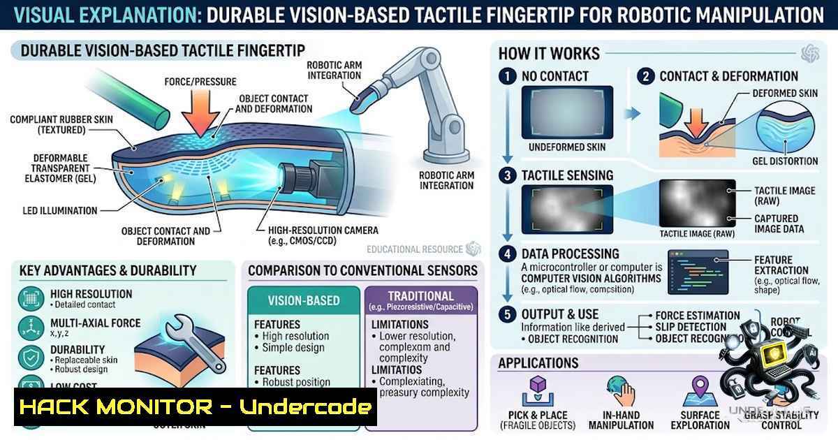
Introduction:
The integration of vision-based tactile sensors in robotic systems marks a significant leap forward in enabling machines to interact with their environment with human-like dexterity. However, the primary bottleneck for widespread adoption has been the fragility of these sensors, which often fail under repetitive contact and abrasive conditions. This article dissects a recent breakthrough in sensor design that addresses durability and maintainability, transforming tactile sensing from a delicate laboratory instrument into a robust tool for industrial automation, robotic manipulation, and AI-driven quality control.
Learning Objectives & Secrets:
- Objective 1: Understand the material science trade-offs in designing a durable tactile sensor, including the role of protective films and adhesives in extending operational lifespan.
- Objective 2 (Secret Tip): Master the fabrication and assembly workflow to ensure optimal adhesion between silicone gel and protective layers, a critical factor often overlooked in commercial designs.
- Objective 3 (Secret Tip): Learn how to interpret damage progression in protective films to implement predictive maintenance, preventing catastrophic sensor failure and reducing downtime.
You Should Know:
1. Sensor Architecture and Material Science Fundamentals
The core innovation lies in the multi-layer construction designed to withstand physical wear. The sensor uses a silicone gel as the deformable medium, overlaid with a textured polyurethane (TPU) protective film. The bonding process relies on a silane treatment to enhance adhesion between the silicone and the TPU, creating a cohesive unit that distributes stress. Unlike rigid commercial sensors that shatter upon impact, this design absorbs energy through the gel, while the TPU film acts as a sacrificial layer.
Step-by-Step Guide: Fabrication and Assembly
- Mold Preparation: Create a textured mold using photolithography or 3D printing to define the sensing surface’s topography. This texture is crucial for detecting shear forces and surface slip.
- Film Application: Apply the polyurethane film (approx. 1-2 mm thickness) onto the mold under controlled temperature to ensure a uniform coating.
- Bonding Process: Prepare the silicone gel base and curing agent. Apply a silane coupling agent (e.g., 3-aminopropyltriethoxysilane) to the inner surface of the TPU film to promote chemical bonding.
- Injection Molding: Inject the silicone gel mixture into the cartridge housing, allowing it to cure against the prepared TPU film.
- Assembly: Secure the cartridge into the sensor housing using a snap-fit mechanism, ensuring an optical path is maintained between the internal camera and the gel surface.
2. Durability Testing and Failure Mode Analysis
The research team subjected the sensor to rigorous abrasion and repetitive probing tests, benchmarking against commercially available alternatives. The results were staggering; commercial sensors failed within 24-30 seconds of abrasive wear. In contrast, the new sensor maintained functionality for 2-3 hours before the TPU film ruptured. Furthermore, during repetitive probing, 7 sensors remained operational after 5 days of continuous use. The study noted a gradual degradation where localized TPU rupture did not immediately compromise tactile imaging, providing a “graceful degradation” that allows for continued operation until maintenance can be scheduled.
Practical Commands and Data Acquisition:
For engineers looking to replicate the testing environment, the following Linux commands can be used to automate data logging from the sensor’s camera feed over USB:
 Install video capture and processing tools
sudo apt-get install v4l-utils ffmpeg
 List video devices to identify the sensor camera
v4l2-ctl --list-devices
 Stream raw video data to a file for timestamped analysis
ffmpeg -f v4l2 -video_size 1280x720 -framerate 30 -input_format mjpeg -i /dev/video0 -vf "drawtext=text='%{pts:gmtime:0:%Y-%m-%d %H:%M:%S}':x=5:y=5:fontsize=24:fontcolor=white" -c:v libx264 -t 3600 sensor_test_$(date +%Y%m%d).mp4
This command captures a one-hour test while overlaying a timestamp, allowing you to correlate visual data with physical wear metrics. For Windows users, equivalent capture can be achieved using the built-in Camera app or OpenCV with Python:
import cv2
cap = cv2.VideoCapture(0)  Adjust index as needed
out = cv2.VideoWriter('sensor_output.avi', cv2.VideoWriter_fourcc('M','J','P','G'), 30, (1280,720))
while True:
ret, frame = cap.read()
if not ret: break
out.write(frame)
cv2.imshow('Sensor Feed', frame)
if cv2.waitKey(1) & 0xFF == ord('q'): break
cap.release(); out.release(); cv2.destroyAllWindows()
3. Advanced Calibration and Data Processing
Once the sensor is assembled, the raw images from the internal camera must be calibrated to map pixel displacement to force vectors. This typically involves using a checkerboard pattern or dot-grid markers embedded in the gel. By tracking the movement of these markers in the XY plane and the intensity changes caused by depth deformation, you can derive normal and shear forces.
Step-by-Step Calibration Procedure:
- Baseline Capture: Record a reference image of the resting gel surface with no external contact.
- Force Application: Apply a known force using a load cell or precision scale (e.g., 0.5N, 1.0N increments).
- Optical Flow Analysis: Use OpenCV’s `calcOpticalFlowFarneback` to compute dense optical flow between the deformed and baseline images. This provides a vector field representing displacement.
import cv2 import numpy as np Load baseline and deformed images baseline = cv2.imread('baseline.png', 0); deformed = cv2.imread('deformed.png', 0) Calculate optical flow flow = cv2.calcOpticalFlowFarneback(baseline, deformed, None, 0.5, 3, 15, 3, 5, 1.2, 0) Extract magnitude and angle for force mapping magnitude, angle = cv2.cartToPolar(flow[..., 0], flow[..., 1]) - Mapping Function: Correlate the maximum displacement magnitude with the applied force to create a linear regression model, yielding a direct force-to-displacement mapping.
4. Integration with Robotic Control Systems
The sensor’s design allows for easy integration into existing robotic arms, particularly those using ROS (Robot Operating System). The replaceable cartridge fits into a standard robotic gripper housing, and the visual data can be published as an image topic. This enables real-time haptic feedback for tasks like peg-in-hole insertion, object grasping, and surface texture classification. The sensor’s ability to maintain tactile imaging even after damage means the robot can continue to operate with reduced precision rather than coming to an abrupt halt.
Cloud and API Security Context:
While the sensor itself is hardware, the data it generates (images, force vectors) is often processed in the cloud for training AI models or stored for quality assurance. When transmitting this sensor data, ensure compliance with industrial cybersecurity standards. Use HTTPS/WebSockets with TLS 1.3 for encrypted transmission. Configure API gateways to handle high-velocity data streams and implement rate limiting to prevent DDoS attacks. For on-premise MLOps pipelines, set up a secure VPN or use Azure Private Link/AWS PrivateLink to keep data off the public internet.
5. Hardening and Maintenance Strategies
The “replaceable cartridge” approach introduces a design pattern akin to hot-swappable components in server racks. For end-users, this means maintaining a spare cartridge inventory and implementing a visual inspection schedule using machine learning to detect early-stage TPU wear. An AI model can be trained on images of the sensor surface to classify wear levels (e.g., “Good”, “Minor Scratch”, “Major Tear”). If a tear is detected, a service request can be automatically triggered.
Suggested Maintenance Script (Windows/Linux):
Create a Python script that continuously analyzes the camera feed for anomalies using histogram analysis. A sudden spike in brightness or a static pattern indicating a tear can trigger an alert.
import cv2, numpy as np
cap = cv2.VideoCapture(0)
while True:
ret, frame = cap.read()
gray = cv2.cvtColor(frame, cv2.COLOR_BGR2GRAY)
hist = cv2.calcHist([bash], [bash], None, [bash], [0,256])
 Check for abnormally high pixel intensity (indicative of a tear or hole)
if np.sum(hist[200:]) > 5000:  Threshold depends on lighting
print("WARNING: Potential sensor damage detected.")
 Log and send alert here
time.sleep(60)  Check every minute
What Undercode Say:
- Key Takeaway 1: The marriage of material science and computer vision is the future of tactile sensing, moving beyond rigid electronics to soft, durable, and replaceable interfaces.
- Key Takeaway 2: Graceful degradation is a superior design philosophy for real-world robotics; a sensor that warns before it breaks is infinitely more valuable than one that simply fails.
- Analysis: The shift from disposable sensors to maintainable modules will significantly reduce the operational costs of automated systems. I see a parallel here with the transition from monolithic software architectures to microservices—modularity allows for faster iteration and easier troubleshooting. Moreover, this technology dramatically lowers the barrier to entry for researchers, as they can fabricate custom textures for specific tasks without manufacturing an entirely new sensor. The gradual damage signal is a hidden gem, enabling self-reporting systems that are crucial for Industry 4.0. This is a prime example where hardware catches up to the software paradigm of continuous deployment and graceful degradation.
Prediction:
- +1 Industry Adoption: Expect to see rapid adoption in high-wear industries such as fruit-picking, logistics sorting, and manufacturing quality assurance, with a 30% reduction in sensor-related downtime by 2027.
- +1 AI Integration: The ability to generate consistent tactile data over long periods will lead to more robust training datasets, significantly improving the performance of grasping and manipulation algorithms.
- -1 Cost Barriers: While the sensor is more durable, the initial fabrication cost may be higher than standard MEMS-based sensors, potentially limiting adoption in low-budget educational settings.
- +1 Standardization: This design will likely become a reference architecture, pushing the entire industry toward standardized cartridge form factors, similar to how batteries have become standardized in consumer electronics.
▶️ Related Video (92% Match):
🎯Let’s Practice For Free:
🎓 Live Courses & Certifications:
Join Undercode Academy for Verified Certifications
🚀 Request a Custom Project:
Secure, high-velocity infrastructure and disruptive technological engineering. Contact our engineering team for high-tier development and proprietary systems:
[email protected]
💎 Smart Architecture | 🛡️ Secure by Design | ⭐ Trusted by Thousands
IT/Security Reporter URL:
Reported By: https://lnkd.in/p/e6bi3cZ6 – Hackers Feeds
Extra Hub: Undercode MoN
Basic Verification: Pass ✅


