Listen to this Post
Introduction:
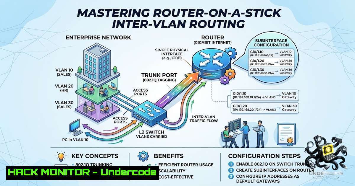
Virtual Local Area Networks (VLANs) are fundamental to network segmentation, allowing administrators to isolate broadcast domains and enforce security policies without altering physical infrastructure. However, for devices in different VLANs to communicate, they require a Layer 3 gateway, which can be provided by a router or a Layer 3 switch. The “Router-on-a-Stick” configuration is a cost-effective method of Inter-VLAN routing that leverages a single physical router interface logically divided into multiple subinterfaces, enabling the routing of traffic between VLANs using IEEE 802.1Q trunking. This article provides a technical deep dive into building this lab environment, complete with configuration syntax, verification commands, and troubleshooting steps, bridging the gap between networking theory and practical implementation.
Learning Objectives:
- Objective 1: Understand the role of IEEE 802.1Q in tagging Ethernet frames for VLAN identification and the concept of router subinterfaces.
- Objective 2: Implement a full Router-on-a-Stick Inter-VLAN routing topology in a lab environment, configuring access ports, trunk ports, and subinterface encapsulation.
- Objective 3: Master verification and troubleshooting commands to validate connectivity and ensure the correct flow of traffic across logical network segments.
You Should Know:
- Subinterfaces and 802.1Q Tagging: A Step-by-Step Configuration Guide
At the heart of the Router-on-a-Stick architecture lies the subinterface. A subinterface is a logical division of a physical router interface, allowing a single GigabitEthernet port to act as the gateway for multiple VLANs. The router uses the 802.1Q encapsulation standard to distinguish which frames belong to which VLAN. The `encapsulation dot1Q` command assigns a VLAN ID to the subinterface, and the router can then see the 4-byte tag added to the Ethernet frame. Here is a step-by-step walkthrough of how to configure this in Cisco IOS:
Step 1: Create Subinterfaces.
Navigate to global configuration mode and specify the physical interface. For example, if using GigabitEthernet0/0, create subinterfaces for VLANs 10 and 20.
Router> enable
Router configure terminal
Router(config) interface gigabitEthernet 0/0.10
Step 2: Set Encapsulation.
Define the VLAN ID for the subinterface. This tells the router to accept traffic tagged with this specific VLAN ID.
Router(config-subif) encapsulation dot1Q 10
Step 3: Assign an IP Address.
The IP address serves as the default gateway for devices in that specific VLAN.
Router(config-subif) ip address 192.168.10.1 255.255.255.0
Step 4: Repeat for Additional VLANs.
Create the second subinterface for VLAN 20.
Router(config) interface gigabitEthernet 0/0.20
Router(config-subif) encapsulation dot1Q 20
Router(config-subif) ip address 192.168.20.1 255.255.255.0
Step 5: Bring the Physical Interface Up.
The physical interface must be active (no shutdown) for the subinterfaces to function.
Router(config) interface gigabitEthernet 0/0
Router(config-if) no shutdown
Verification Commands:
– `show ip interface brief` – Confirm that the subinterfaces are up and configured with the correct IP.
– `show interfaces gigabitEthernet 0/0.10` – Verify the encapsulation method and ensure the interface is not in a down state.
– `show running-config` – Review the entire configuration to ensure no syntax errors exist.
Troubleshooting Tip: If devices cannot communicate, check that the VLANs are correctly created on the switch and that the router’s subinterface IP is set as the default gateway for the client machines. Ensure the switch port connected to the router is in trunk mode.
2. Switch Configuration: Access Ports, VLANs, and Trunking
The switch’s role in this topology is to segregate traffic into VLANs and send tagged traffic to the router. This requires assigning VLANs to specific ports and establishing a trunk link. A trunk port is essential because it carries traffic for multiple VLANs, preserving the 802.1Q tags that the router relies on for subinterface classification.
Step 1: Create VLANs.
On the switch, define the VLANs you intend to use.
Switch> enable
Switch configure terminal
Switch(config) vlan 10
Switch(config-vlan) name Sales
Switch(config) vlan 20
Switch(config-vlan) name Engineering
Step 2: Configure Access Ports.
Assign the ports connected to end devices (e.g., PCs) to the appropriate VLANs.
Switch(config) interface fastEthernet 0/1
Switch(config-if) switchport mode access
Switch(config-if) switchport access vlan 10
Switch(config) interface fastEthernet 0/2
Switch(config-if) switchport mode access
Switch(config-if) switchport access vlan 20
Step 3: Configure the Trunk Port.
The port connecting to the router must be configured as a trunk. It is standard practice to explicitly allow specific VLANs rather than allowing all by default to enhance security.
Switch(config) interface gigabitEthernet 0/1
Switch(config-if) switchport mode trunk
Switch(config-if) switchport trunk allowed vlan 10,20
Verification Commands on the Switch:
– `show vlan brief` – Confirm that the VLANs are created and that ports are correctly assigned.
– `show interfaces trunk` – Ensure the desired VLANs are listed in the allowed list and active.
3. Host Configuration and Connectivity Testing
Once the network infrastructure is set, the final step is to configure the hosts (PCs) to use the router’s subinterface IP as the default gateway. For instance, a PC in VLAN 10 should have an IP of `192.168.10.2/24` with a default gateway of 192.168.10.1. A PC in VLAN 20 would have `192.168.20.2/24` with a gateway of 192.168.20.1.
Testing:
– `ping 192.168.20.1` (from VLAN 10 PC) – This tests reachability to the router’s subinterface for VLAN 20.
– `ping 192.168.20.2` (from VLAN 10 PC) – This tests end-to-end Inter-VLAN connectivity.
Troubleshooting Commands (Linux/Windows):
- Linux/Windows: `ipconfig` or `ip a` – Ensure the IP and gateway are correctly applied.
- Windows: `route print` – Verify that the default gateway is set correctly in the routing table.
- Linux: `ip route show` – Display the routing table to confirm the default route.
- Advanced Diagnostic: If pings fail, use `traceroute` (Linux) or `tracert` (Windows) to identify the hop where the packet is being dropped. This helps isolate whether the issue lies in the switch’s VLAN assignment, the trunk, or the router’s subinterface configuration.
4. Security Hardening and Best Practices
While the basic lab focuses on connectivity, network engineers must consider security implications. Trunk ports are high-value targets; an attacker could attempt VLAN hopping if not properly secured.
– Trunk Hardening: Always explicitly specify the allowed VLANs using switchport trunk allowed vlan {list}. Never leave the native VLAN as VLAN 1 without enforcing a matching policy on the router.
– Native VLAN: By default, 802.1Q uses a native VLAN (usually VLAN 1) for untagged traffic. To avoid mismatches, set a different, unused VLAN as the native VLAN on both the switch and the router subinterface (e.g., encapsulation dot1Q 99 native).
– Loop Prevention: Ensure Spanning Tree Protocol (STP) is functioning correctly to prevent network loops, especially when implementing redundant links.
– Access Control Lists (ACLs): To restrict communication between specific VLANs, apply ACLs on the router subinterfaces. For example, a standard ACL can prevent Engineering from accessing Sales databases while still allowing other traffic.
- Extending the Lab: Linux and Windows Network Interaction
Understanding how hosts interact with the network can be enhanced by simulating the lab using virtual machines (VMs) connected to the Cisco Packet Tracer network or a physical switch. Here are some relevant commands that network administrators should be familiar with for host-based diagnostics:
- Linux Bonding (for trunk-like redundancy): While not directly related to Router-on-a-Stick, understanding interface configuration is key.
ip link add bond0 type bond mode 802.3ad
ip link set eth0 master bond0
- Windows Network Configuration: For advanced troubleshooting, resetting the network stack using `netsh int ip reset` can resolve misconfigurations.
- Capturing Traffic: Use `tcpdump` (Linux) or Wireshark to capture traffic on the router’s physical interface to observe the 802.1Q tags being sent and received. This provides a powerful visual confirmation of the encapsulation process.
What Undercode Say:
- Key Takeaway 1: Subinterfaces break down a single physical connection into multiple logical gateways, efficiently solving the issue of limited router interfaces in small to medium-sized networks.
- Key Takeaway 2: Hands-on configuration clarifies the dependency between switch trunk ports and router encapsulation—if the tags don’t match (e.g., different VLAN IDs), communication fails instantly.
Analysis: This lab is a rite of passage for network engineers. While the concept of VLANS seems simple on paper—separating traffic—the practical mechanics of tagging, trunking, and routing can be daunting. The successful implementation of this lab requires a systemic understanding: that a layer 2 frame needs a layer 3 header to traverse routers, and 802.1Q is the “shipping label” that ensures it gets to the right virtual receiver. Often, professionals memorize commands without understanding the frame flow; completing this lab forces a visualization of the data path that is invaluable. It also highlights that a modern cyber defense often relies on these VLANs to contain threats; if a misconfiguration exists, an attacker can easily pivot between logical networks.
Prediction:
- +1 The demand for engineers proficient in hybrid network architectures (combining traditional VLANs with SDN overlays) will rise significantly as enterprises modernize their infrastructure.
- +1 As automation becomes ubiquitous, the underlying knowledge of manual configurations like Router-on-a-Stick remains critical for troubleshooting automated deployments, ensuring the “why” behind infrastructure-as-code remains understood.
- -1 However, the increasing complexity of cloud-1ative networking (e.g., CNI plugins for Kubernetes) may reduce the frequency of physical Router-on-a-Stick implementations, creating a skill gap if not addressed with modernized training.
- +1 The integration of AI-driven network management tools will likely use these simple lab topologies as training datasets to predict routing failures before they impact production.
- -1 Reliance on virtualized environments might lead to a generation of engineers who understand the commands but lack the muscle memory for physical cabling and physical layer troubleshooting, potentially increasing resolution times for physical network faults.
▶️ Related Video (72% Match):
🎯Let’s Practice For Free:
🎓 Live Courses & Certifications:
Join Undercode Academy for Verified Certifications
🚀 Request a Custom Project:
Secure, high-velocity infrastructure and disruptive technological engineering. Contact our engineering team for high-tier development and proprietary systems:
[email protected]
💎 Smart Architecture | 🛡️ Secure by Design | ⭐ Trusted by Thousands
IT/Security Reporter URL:
Reported By: https://lnkd.in/p/eM_ttYNN – Hackers Feeds
Extra Hub: Undercode MoN
Basic Verification: Pass ✅


