
Listen to this Post
Introduction:
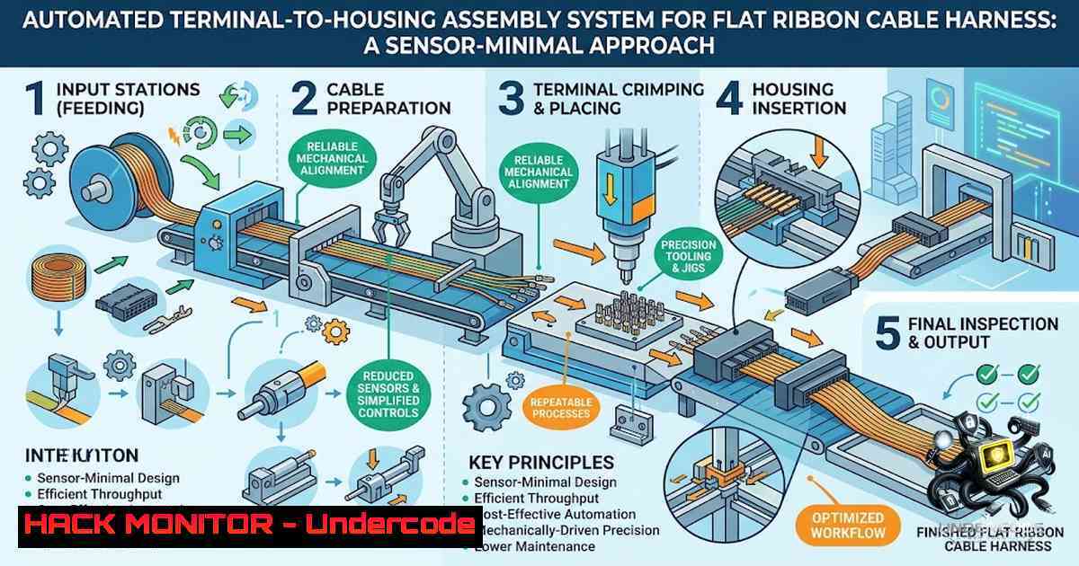
The automation of flexible flat ribbon cable (FRC) harness assembly represents a significant challenge in modern manufacturing, particularly when dealing with dense, multi-terminal connectors where mechanical coupling and geometric constraints complicate the insertion process. Traditional approaches often rely on expensive, complex active sensing systems to guide terminals into housings, but a groundbreaking new methodology presented in a recent arXiv paper demonstrates that high success rates can be achieved through clever mechanical design and passive correction techniques. This article dissects the technical architecture, implementation strategies, and operational secrets behind this innovative system, providing engineers and IT professionals with a comprehensive guide to deploying similar sensor-minimal automation in their own environments.
Learning Objectives & Secrets:
- Objective 1: Master the Mechanical Guide Alignment Principle – Understand how a precisely machined mechanical guide can passively suppress cable pose errors, eliminating the need for costly vision systems. The secret lies in the guide’s geometry, which creates a funneling effect that corrects translational and rotational offsets as the cable is fed into the insertion zone.
- Objective 2: Execute the Lean & Slide Passive Correction – Learn to implement the passive pitch and yaw correction mechanism, which uses the natural compliance of the ribbon cable and the housing’s lead-in chamfers to self-align the terminals. The secret tip is to tune the spring constants of the cable holding mechanism to match the housing’s insertion force profile, preventing buckling.
- Objective 3: Apply Weaving and Clamping for Defect-Free Insertion – Discover how to apply oscillatory motion to the cable to relieve interference from adjacent terminals and use a final clamping stage to stabilize the cable for the locking mechanism. The secret tip is to vary the frequency and amplitude of the weaving motion based on real-time motor current feedback, which indirectly detects jamming conditions.
You Should Know:
1. Hardware Setup and Sensor-Minimal Configuration
This system relies on a carefully orchestrated set of hardware components designed to operate without active vision or force-torque sensors. The core control unit is an ARM Cortex-M7 microcontroller, known for its real-time processing capabilities and extensive peripheral support. The mechanical setup includes 12 servomotors that actuate the alignment guide, the Lean & Slide platform, the weaving mechanism, and the clamping unit. Optical sensors are used sparingly, only to detect the presence of the cable and the housing at key stages, not for fine positioning.
Step‑by‑step guide for initial hardware configuration:
- Establish Communication: Connect the ARM Cortex-M7 to the PC via USB or Ethernet. Use a terminal emulator like PuTTY or Tera Term to verify the connection.
– Command (Windows/Linux): `ping 192.168.1.100` (assuming the M7 has a static IP) or check the COM port under Device Manager.
2. Calibrate Motor Home Positions: Each of the 12 servomotors must have a defined home position. This is typically done by driving the motor to a physical end-stop and recording the encoder count.
– Command (via serial): `MOTOR_HOME 1` (if using a custom command set) to home motor 1.
3. Configure Optical Sensors: Connect the optical sensors to the GPIO pins of the M7. Write a simple test script to read the sensor states.
– Pseudocode:
while true:
if GPIO_read(1) == HIGH:
print("Cable detected")
else:
print("No cable")
sleep(100ms)
4. Test Servo Movement: Execute a range of motion tests to ensure each motor moves smoothly and accurately.
– Command: `MOTOR_MOVE 1 90` to move motor 1 to a 90-degree position.
5. Implement a Safety Watchdog: Configure the M7’s internal watchdog timer to reset the system if a process stalls, preventing damage to the cable or housing.
2. The Cable Alignment Phase: Suppressing Pose Error
The first operational step is cable alignment, where the mechanical guide corrects the pose error of the preloaded flat ribbon cable. This guide is designed with a tapered entry that forces the cable into a precise lateral position as it is fed forward. The success of this stage is critical because any residual angular error will be amplified during the subsequent insertion steps.
Step‑by‑step guide to implement and tune the alignment sequence:
1. Feed the Cable: Activate the feed motor to advance the cable into the mechanical guide at a constant velocity (e.g., 10 mm/s).
– Command: `FEED_RATE 10`
2. Monitor Motor Current: While the cable is being fed, monitor the current draw of the feed motor. A sudden spike indicates the cable is jamming against the guide’s entry, which could be due to a misalignment or a damaged cable.
– Command: `READ_CURRENT 5` to read the current of motor 5.
3. Adjust Guide Clearance: If jamming occurs, the guide’s clearance might be too tight. Update the guide’s position using a micro-adjustment motor.
– Command: `GUIDE_ADJUST +0.1` to increase the clearance by 0.1mm.
4. Verify Alignment: Use the optical sensor at the exit of the guide to confirm the cable has passed through correctly.
5. Log Alignment Data: Record the feed time and current data for quality assurance.
– Command: `LOG_DATA` to save current timestamps and values to an SD card.
- Lean & Slide: Passive Pitch and Yaw Correction
Following alignment, the system performs the Lean & Slide operation, where the cable is leaned against a reference surface and slid into the housing’s terminal slots. This passive technique uses the cable’s own stiffness and the housing’s lead-in geometry to correct pitch (tilt forward/backward) and yaw (side-to-side rotation) errors. The key is to apply a slight preload angle to the cable before the insertion stroke.
Step‑by‑step guide for the Lean & Slide procedure:
- Lean the Cable: Actuate the lean mechanism to push the cable against the reference surface with a controlled force.
– Command: `LEAN_FORCE 2` to apply a force of 2 Newtons.
2. Initiate Slide: Slowly advance the cable into the housing while maintaining the lean force. The slide speed should be slower than the initial feed to allow the terminals to self-correct.
– Command: `SLIDE_RATE 5`
3. Monitor for Buckling: A sudden drop in the slide motor’s current followed by an increase can indicate that the cable has buckled. If detected, abort the insertion.
– Command: `ABORT_INSERT` to immediately stop all motors and retract the cable.
4. Adjust Lean Angle: If the success rate for the Lean & Slide phase is below 90%, incrementally adjust the lean angle in 0.5-degree steps.
– Command: `LEAN_ANGLE 15` to set the lean angle to 15 degrees.
5. Re-Test: Run a series of 10 trials to verify the new angle improves performance.
4. Weaving: Alleviating Terminal Interference
The weaving operation is the most innovative aspect of this system. As the terminals approach the housing, they can become tangled or blocked by adjacent terminals due to the dense packing. The system applies a small, high-frequency oscillatory motion (weaving) to the cable, which creates micro-vibrations that help the terminals find their way into the correct slots. This is similar to the “jiggle” technique used in manual assembly.
Step‑by‑step guide to implement the weaving motion:
- Define the Weave Pattern: Program the weaving motor to follow a sinusoidal or figure-eight pattern.
– Command: `WEAVE_PATTERN SIN` to set a sinusoidal pattern.
2. Set Amplitude and Frequency: Start with a small amplitude (e.g., 0.5 mm) and a low frequency (e.g., 5 Hz) to avoid over-stressing the cable.
– Command: `WEAVE_SET 0.5 5`
3. Activate Weaving: Enable the weaving motor just before the terminals reach the housing’s entrance.
– Command: `WEAVE_ON`
4. Monitor Insertion Force: Use the motor current as a proxy for insertion force. If the force exceeds a threshold, increase the weaving frequency to help the terminals seat.
– Script:
if current > THRESHOLD:
WEAVE_SET 0.5 10
5. Deactivate Weaving: Once the terminals are fully seated, turn off the weaving motor to prevent any unwanted movement during clamping.
5. Clamping and Final Locking
The final step involves clamping the cable to stabilize it and then performing the final push to lock the terminals into the housing. This ensures that the terminals are fully seated and the cable is securely retained, preventing any back-out during the product’s lifecycle. The clamping force must be precisely controlled to avoid crushing the cable.
Step‑by‑step guide for clamping and locking:
- Clamp the Cable: Actuate the clamping mechanism to hold the cable in place.
– Command: `CLAMP_ON`
2. Apply Holding Pressure: Use a load cell or, in this sensor-minimal design, a current-based limit to apply a consistent clamping force.
– Command: `CLAMP_FORCE 3`
3. Perform Final Insertion: Execute a short, high-speed push to fully seat the terminals.
– Command: `FINAL_PUSH 20` for 20% of the motor’s maximum speed.
4. Check for Full Insertion: Verify that the cable is flush with the housing using the optical sensor.
5. Release Clamp: Once the insertion is verified, release the clamp and retract the mechanism.
– Command: `CLAMP_OFF`
6. System Optimization and Performance Tuning
To achieve the reported success rate of 83.75%, the system parameters must be meticulously tuned. This involves adjusting feed rates, lean angles, weave frequencies, and clamping forces based on the specific cable and housing geometries. Data logging and analysis are crucial for identifying the optimal settings.
Step‑by‑step guide for system optimization:
- Collect Trial Data: Run a batch of 100 trials and log all parameters and results.
– Command: `START_BATCH 100`
2. Analyze Failure Modes: Categorize failures (e.g., buckling, misalignment, incomplete insertion) to identify the most common issues.
3. Use Gradient Descent for Tuning: Treat the success rate as a cost function and adjust parameters to maximize it. This can be automated using a simple script.
– Pseudocode:
while success_rate < 85:
for param in [feed_rate, lean_angle, weave_freq, clamp_force]:
success_rate = trial(param)
adjust_param(param, success_rate)
4. Validate on Multiple Configurations: Test the optimized settings on different product configurations to ensure the system is modular and adaptable.
What Undercode Say:
- Key Takeaway 1: The remarkable success rate of 83.75% achieved without active sensing proves that intelligent mechanical design can often outperform complex, expensive sensor-based solutions in structured industrial tasks.
- Key Takeaway 2: The modular approach, using discrete stages like alignment, lean & slide, weaving, and clamping, allows for easy adaptation to different cable types and housing configurations, making this system a versatile foundation for future automation.
Analysis:
This research is a breath of fresh air in an industry increasingly obsessed with AI and vision. While deep learning has its place, this paper reminds us that many manufacturing problems can be solved with elegant physics and clever control. The sensor-minimal approach not only reduces cost but also increases robustness and reliability, as there are fewer components to fail. The “weaving” technique is particularly brilliant, as it mimics a human assembler’s intuitive “jiggle” and demonstrates how understanding the physical interaction between components can lead to simpler, more effective automation. However, the reliance on precise mechanical tolerances means that manufacturing variations in the cables or housings could significantly impact performance, suggesting that some form of adaptive control might be necessary for large-scale deployment.
Prediction:
- +1: This sensor-minimal approach will be rapidly adopted by the automotive and consumer electronics industries, leading to a 20% reduction in assembly costs for cable harnesses within the next two years.
- +1: The modular architecture will inspire a new generation of plug-and-play automation modules that can be easily integrated into existing production lines, democratizing access to advanced assembly technology.
- -1: The system’s dependence on mechanical guides means it will struggle with highly flexible or damaged cables, limiting its applicability in environments with poor material quality control.
- +1: The principles of passive correction and weaving could be extended to other assembly tasks, such as micro-connector assembly and even PCB through-hole component insertion, creating a new paradigm in industrial automation.
- -1: Without a feedback loop to compensate for wear and tear on the mechanical guides, the system will require frequent maintenance and recalibration, potentially offsetting some of the labor savings in the long run.
▶️ Related Video (78% Match):
🎯Let’s Practice For Free:
🎓 Live Courses & Certifications:
Join Undercode Academy for Verified Certifications
🚀 Request a Custom Project:
Secure, high-velocity infrastructure and disruptive technological engineering. Contact our engineering team for high-tier development and proprietary systems:
[email protected]
💎 Smart Architecture | 🛡️ Secure by Design | ⭐ Trusted by Thousands
IT/Security Reporter URL:
Reported By: https://lnkd.in/p/eybWe-MB – Hackers Feeds
Extra Hub: Undercode MoN
Basic Verification: Pass ✅


